Having quite a bit of experience with DCC Conversions I shared a lot of my projects with fellow enthusiasts . Every new locomotive that I converted I took plenty of pictures as this sometimes helps with putting things back together or trying to solve small problems with wiring or light bleeding out from the lamps or LEDs. The PDFs I created are a great tool when planning a conversion or give an insight into how the loco comes apart. The more modern models are more difficult to pull apart as manufacturers seem to be using more clip together and less screws! I enjoy fixing and converting the locos, recycling older models so they can perform on DCC is one of my pleasures. I have bought second hand locos just so I can convert them. One day I may make it through the entire Fleischmann back catalogue. The early locomotives had many variations, different motors, differing methods of assembly. I have bought many locomotives that were non runners but I have not had one that I have not managed to get working properly without replacing the motor. Sometimes a lot of cleaning is involved. One of the PDFs covers basic fault finding and maintenance.
I thought I would share this DCC Conversion I have done and the "How To" that I have been working on.
Fleischmann Ltd Ed HO 4872 BR 03 Streamlined
Installation of a M1 Decoder
Installation of a M1 Decoder
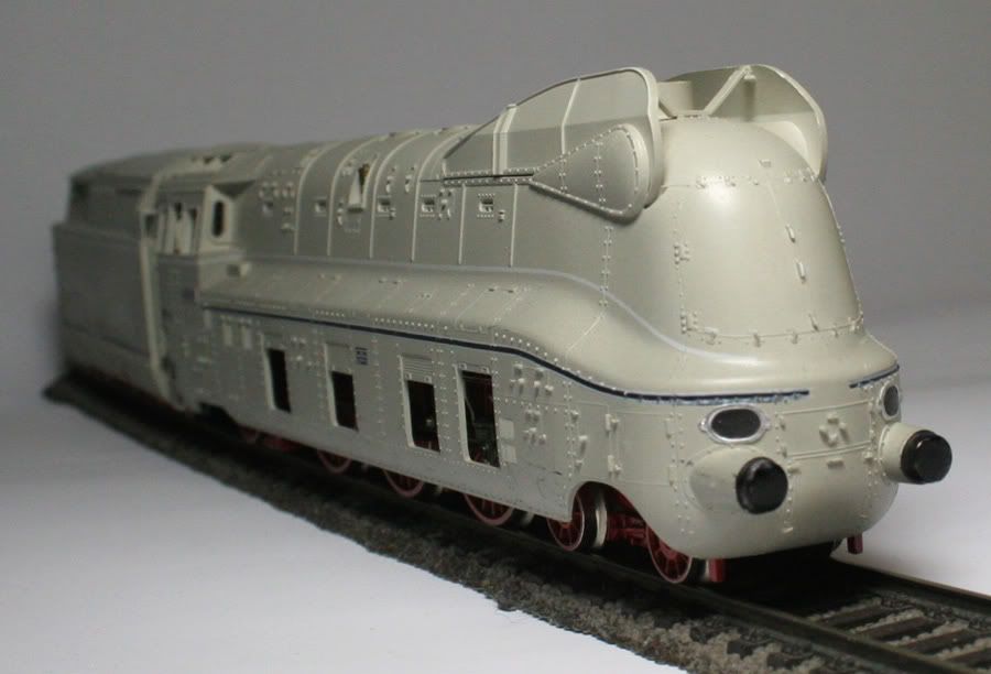
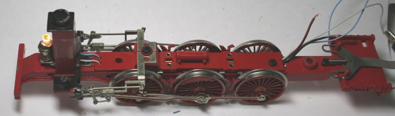
This is a Tender driven locomotive with power pickups on 6 wheels of the locomotive and 4 wheels of the tender.
Turn the Loco upside down to locate the screws holding the body to the chassis
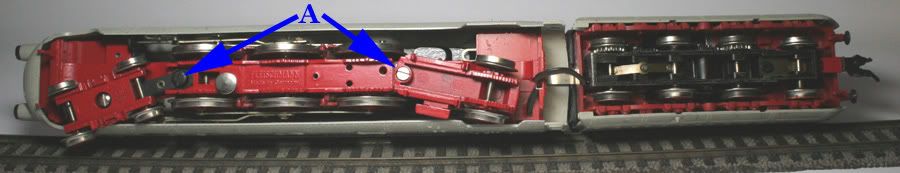
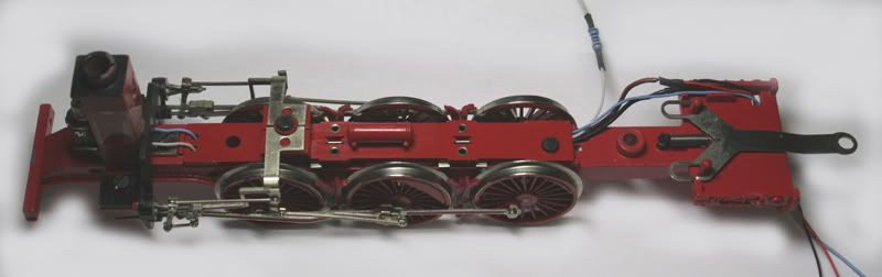
Remove the 2 screws A and remove the leading wheel and trailing wheel trucks from the locomotive.
Next remove screw B .This will allow the body of the Locomotive to be lifted off.
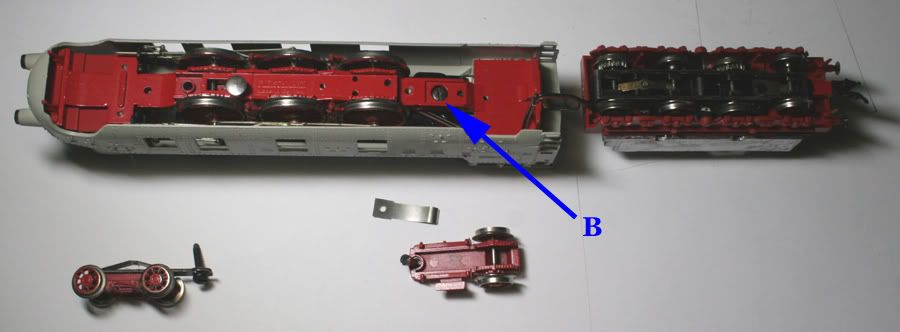
Lift off the Tender body off by easing the 4 clips where the body meets the chassis, this will lift straight up.
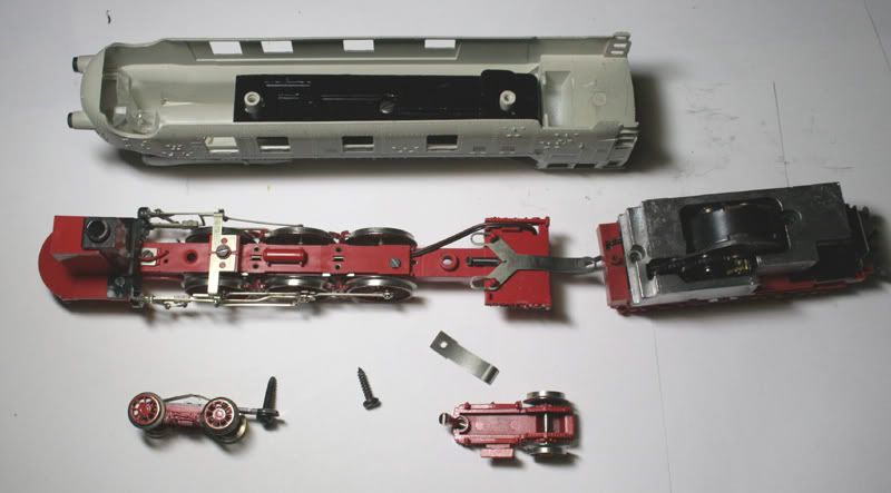
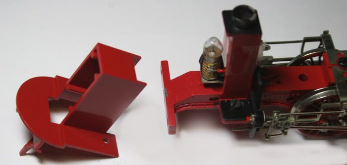
The following picture shows the Locomotive and Tender bodies removed from the chassis.
Lift of the weight and Remove the wiring from the tender.
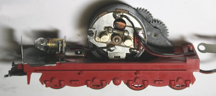
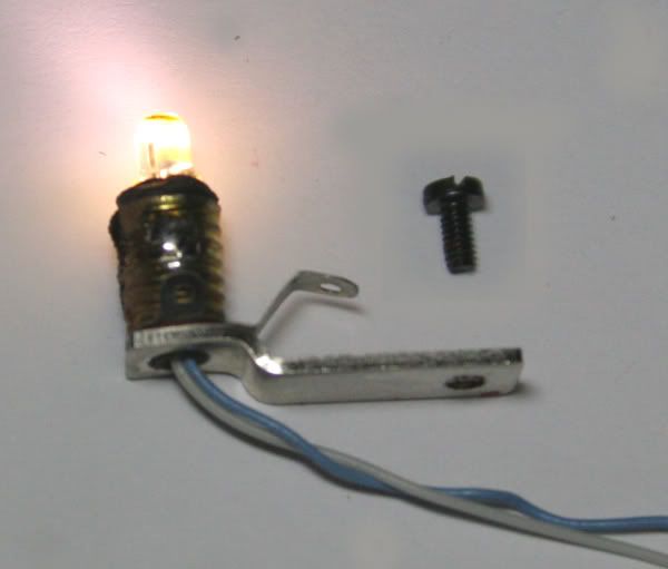
Unscrew the bulb (or Lamp).
I find the best method is to heat the lampholder up with a soldering iron and then unscrew the lamp with a pair of needle nose pliers
Replace the lamp with an LED. Feed the wires through the small hole in the Lampholder
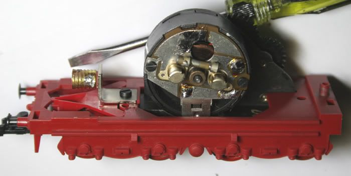
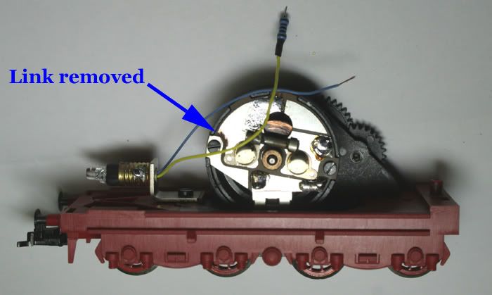
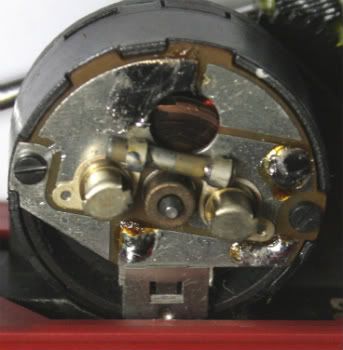
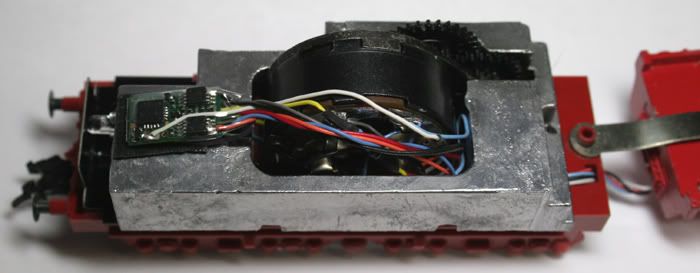
The Picture above shows all wiring removed from the motor .
There is a link that needs to be cut with a Dremel or similar.
I will go over this in more detail further on in this description.
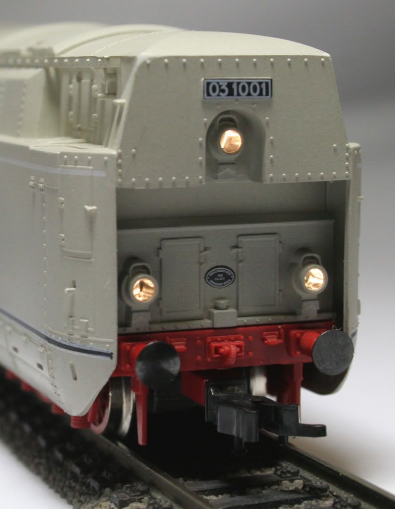
Lighting Replacement
Rear light LED in place
Remove the front light plastic cover, this slides up and forward.
Remove the lamp and wiring.
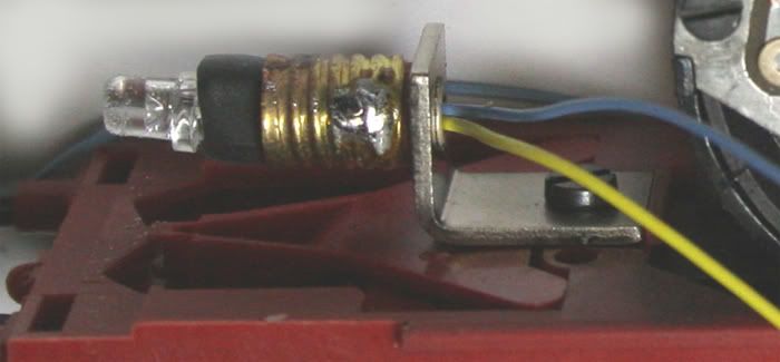
Above– the front LED in the original lamp holder. Extra TCS decoder wire is worth buying just for adding lighting to locomotives.
Note the blue and white wire passing through the hole in the bottom of the lampholder.
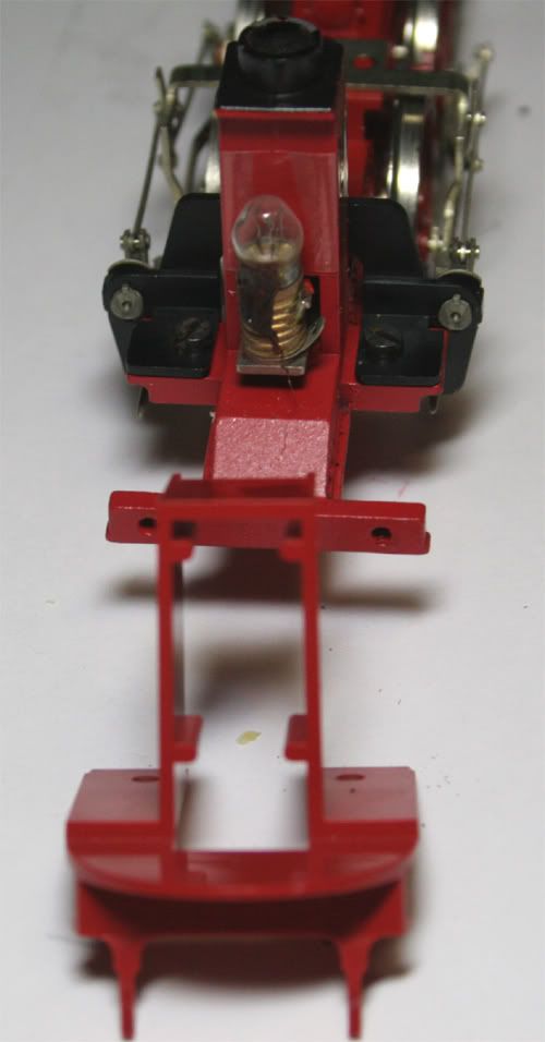
To feed the front LEDs wiring through the chassis the pickups have to be removed from the chassis
Unscrew the two screws holding this in place
The valve gear can be moved slightly out of the way.
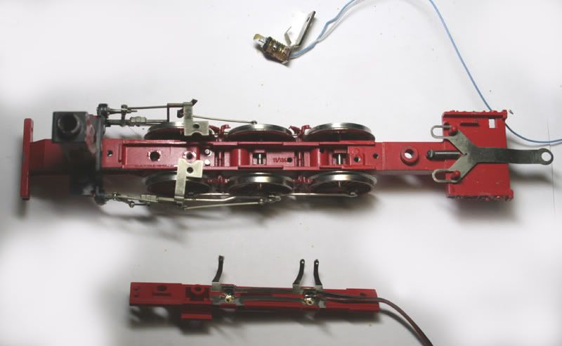
Above - Locomotive power pickups and chassis ready for front lighting wiring.
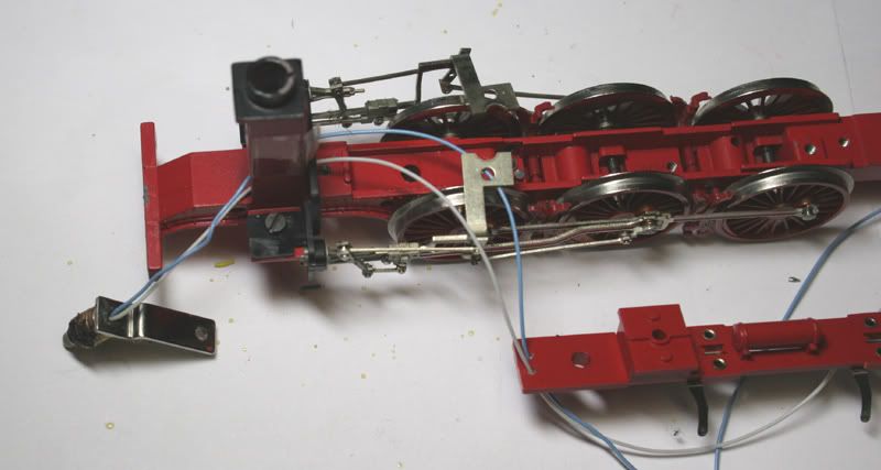
Feed the Blue and White through the chassis and through the holes in the pickup holder, as shown above.
Put the plastic cover with the pickups back in place and test that the wiring is OK. Check that the valve gear is still moving correctly also.
Check 1,2
Add a 1k Ohm Resistor to the white wire, extend the pickup wires with some Red and Black decoder wire. This will be looped to the Tender pickups later. Feed the wiring through the path of the original wiring as shown below.
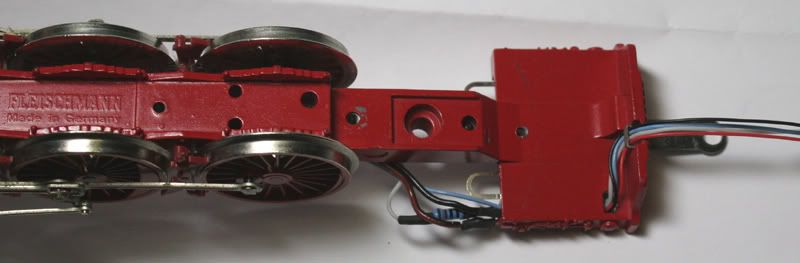
Above – Modified back plate
Below- Before
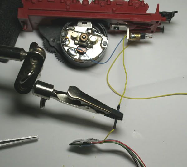
Nearly all the wiring will be soldered to the motor back-plate, this makes maintenance of the locomotive easier.
Below - this is the easiest way to solder the wiring onto the motor terminals , the "helping hands" is great for holding onto resistors , and aid in making good joints . I also use the self-gripping tweezers to hold the wire and solder against a white background to make it easier to see

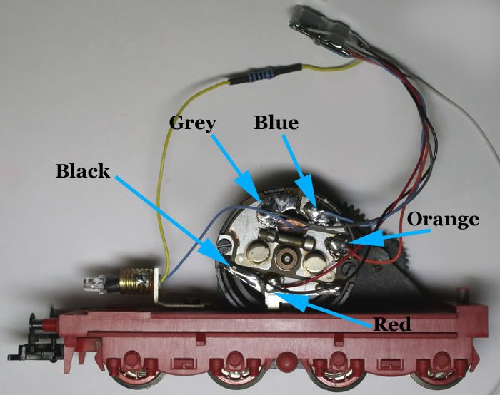
Above- Decoder wiring in place
Note the Blue wire has been soldered to the PCB circuit board , on an unused section.
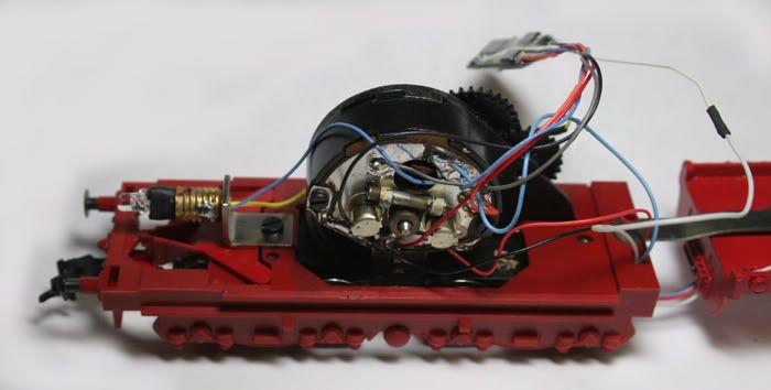
Above- wiring from the Locomotive fed through the tender chassis and connected to the motor back-plate
Connect the white wire (from the front light) to the decoder harness.
Replace the tender weight.
Below-Fix the decoder in place with some double sided tape on the rear of the tender weight.
Put the loco on the programming track and if all is OK put the body back on.
Some more Pictures
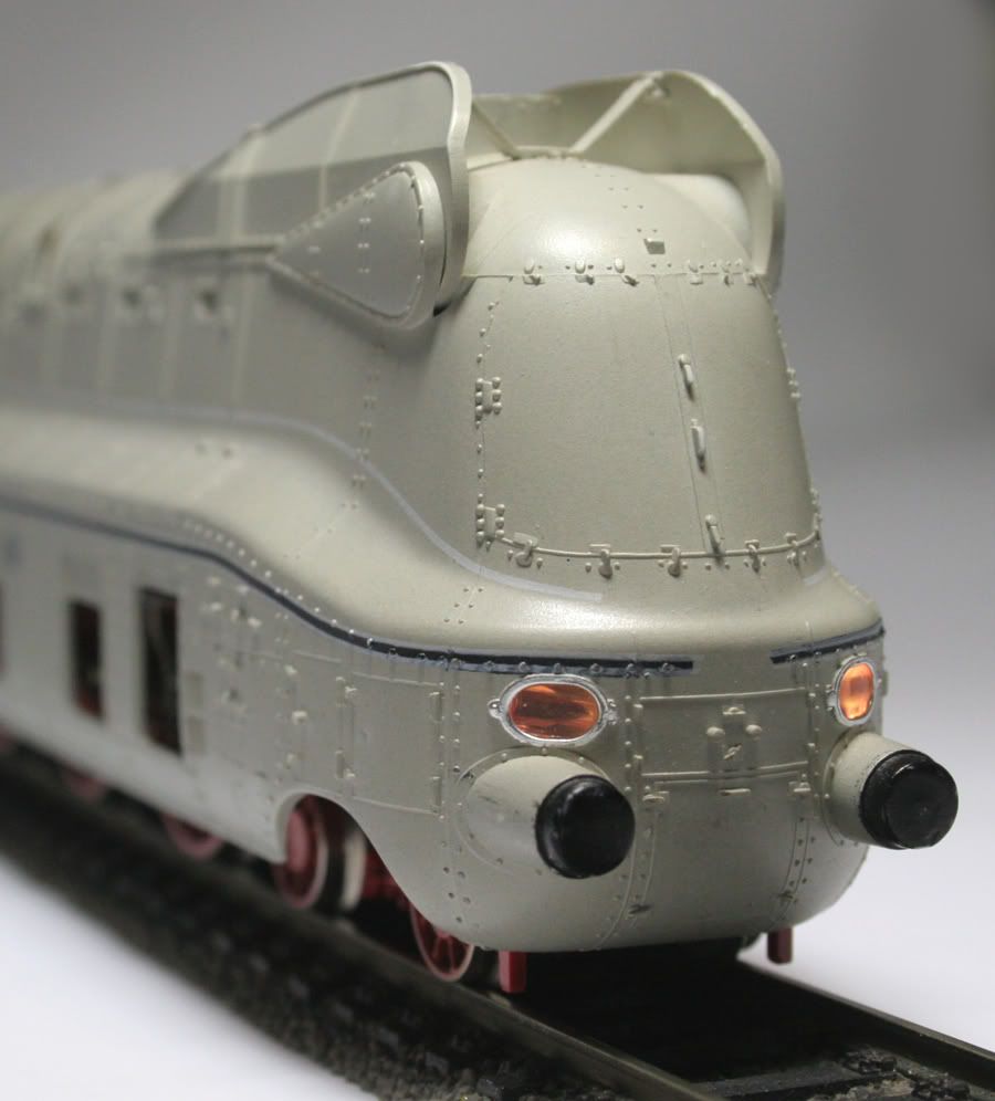
Thanks for looking
No trivia good
ReplyDeleteThank you
ReplyDelete