The last item I have had on my workbench is a Fleischmann BR614 DMU Set #4438 This one was fitted with a Lenz decoder but the installer had taken a few short cuts - the soldering was not to good either. The loco would not run very well at all.
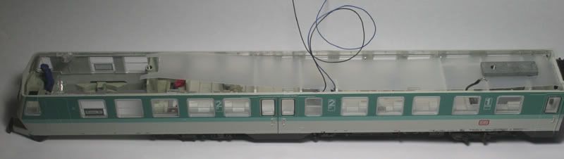
With the lid of (roof can be removed quite easily - I usually start at the rear of the car and work forward unclipping the roof)
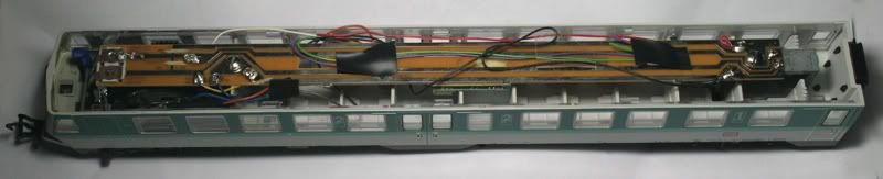
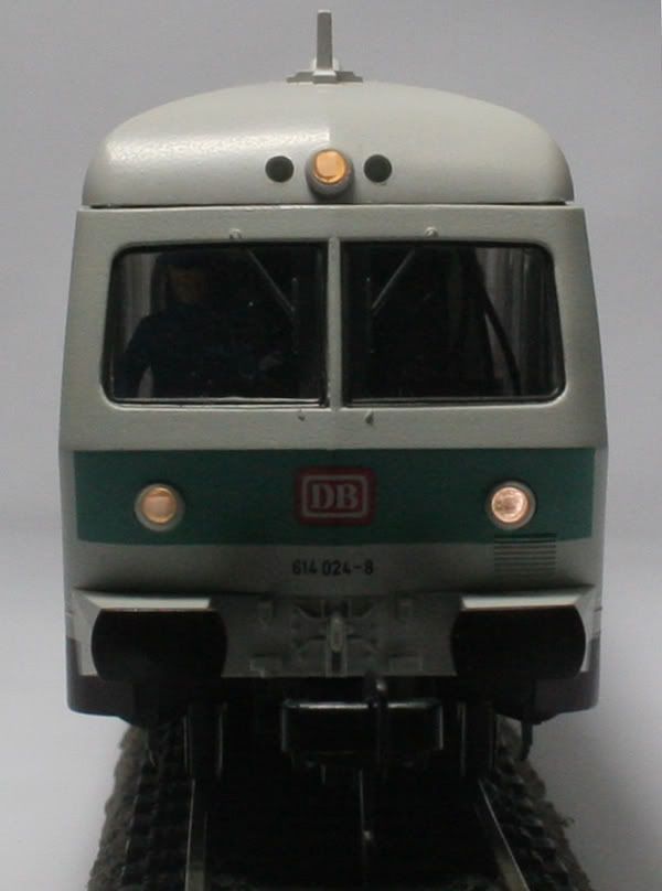
As you can see the wiring hangs down into the cab area and is visible through the windows.
First thing is to remove the wiring , motor bogie , lamps contact brackets , lamps , main circuit board.
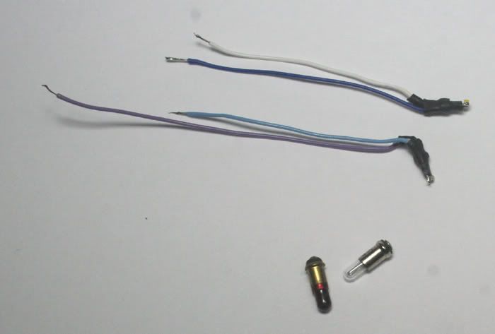
Previously I had made up some mini lamp replacements with SMDs soldered to resistors.
4 of each Warm White and Red for 2 sets of DMUs
Next I had a look at the Motor bogie to Clean the contacts and pickups.
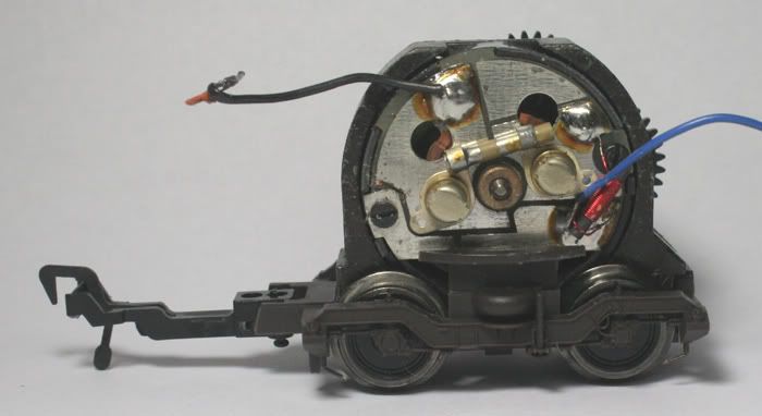
This is where I had discovered that the pickups on the motor bogie had been removed
No wonder it was a poor runner!
I had replacements - there is one that contacts the axles and another that contacts the back of the wheels (on the left hand side)
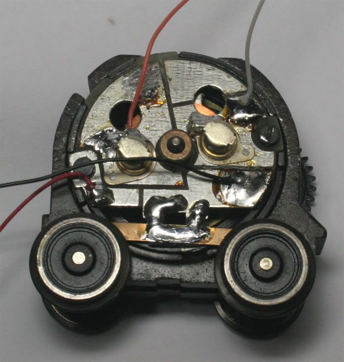
Lately I have been soldering the pickups to the PCB and soldering the Brush holders to the PCB as well. I had a couple of locos that would work fine - then the next day would not run - soldering the brush holders to the PCB fixed poor contact.
This is where I had discovered that the pickups on the motor bogie had been removed
No wonder it was a poor runner!
I had replacements - there is one that contacts the axles and another that contacts the back of the wheels (on the left hand side)
Lately I have been soldering the pickups to the PCB and soldering the Brush holders to the PCB as well. I had a couple of locos that would work fine - then the next day would not run - soldering the brush holders to the PCB fixed poor contact.
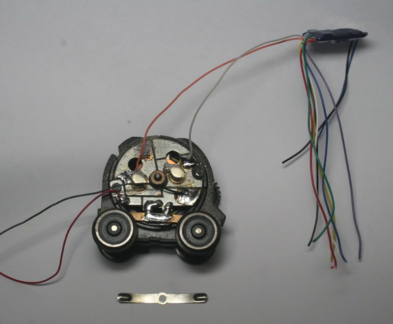
The powered unit now has pick up on all 8 wheels (although 2 have traction tyres)
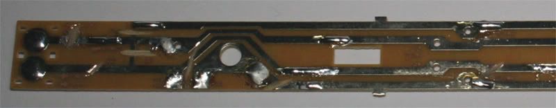
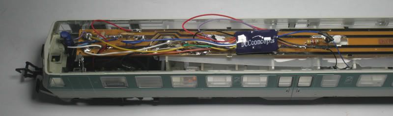
Next thing is the PCB that is inside the roof of the DMU

a few cuts with a Dremel to isolate the various sections . Holding the Dremel lightly against the PCB is all that is required . Too much pressure will cut straight through. Safety first- wear some eye protection! These blades spin at high RPM and I have had a few of the thin ones break up during use.
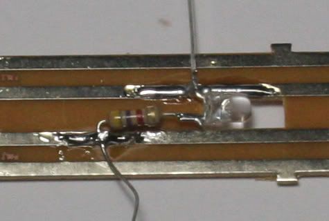
and some LEDs and resistors for internal lighting. I usually clean the track first and pre-tin the track before solding the LED in place. This makes sure that the LED does not absorb unnecessary heat. leaving the tail in place also helps in drawing the heat away from the components.
Next thing is the PCB that is inside the roof of the DMU
a few cuts with a Dremel to isolate the various sections . Holding the Dremel lightly against the PCB is all that is required . Too much pressure will cut straight through. Safety first- wear some eye protection! These blades spin at high RPM and I have had a few of the thin ones break up during use.
and some LEDs and resistors for internal lighting. I usually clean the track first and pre-tin the track before solding the LED in place. This makes sure that the LED does not absorb unnecessary heat. leaving the tail in place also helps in drawing the heat away from the components.
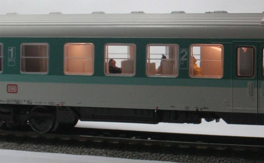
Painting the backs of the LEDs with white paint helps put the light in the correct place.
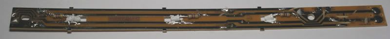
I added a diffuser (made from a plastic milk container) I also add a little white paint to this around the areas that the LEDs are.
You can spot the wires from the Stay Alive unit (This is painted white and held secure with double sided sticky tabs in the toilet)
I added a diffuser (made from a plastic milk container) I also add a little white paint to this around the areas that the LEDs are.
You can spot the wires from the Stay Alive unit (This is painted white and held secure with double sided sticky tabs in the toilet)
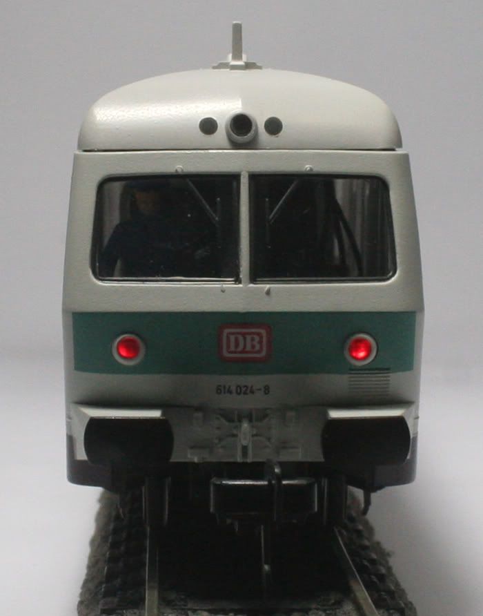
Next the front lights are put in place and tested- then the motor bogie put back in before the PCB is put back in place.
These DMUs are wired a little differently than the conventional Fleischmann locos
Fleischmann locos generally are pushed (with the motor at the rear) and these are pulled (driver at the front and motor just behind him)
The motor body is connected to the Right hand rail pickups and the orange wire goes to the left hand side of the motor.
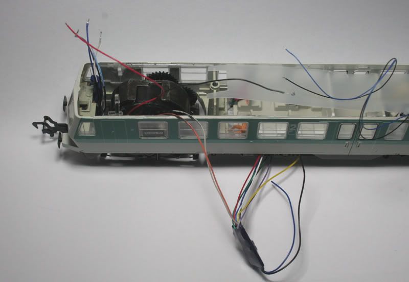
I paint all the visible wires black inside the cab area
I tend to leave enough wire for the motor to be pulled out for servicing so the extra is folded above the PCB
These DMUs are wired a little differently than the conventional Fleischmann locos
Fleischmann locos generally are pushed (with the motor at the rear) and these are pulled (driver at the front and motor just behind him)
The motor body is connected to the Right hand rail pickups and the orange wire goes to the left hand side of the motor.
I paint all the visible wires black inside the cab area
I tend to leave enough wire for the motor to be pulled out for servicing so the extra is folded above the PCB
A few pictures of the motorized end
No comments:
Post a Comment