Roco HO 4178B Re 4/4
Installation of a DCCconcepts Decoder
Installation of a DCCconcepts Decoder

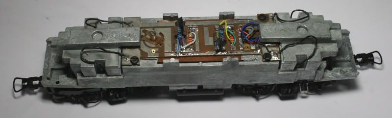
This locomotive has a centrally mounted motor, carden-shaft driven bogies at both ends with power pickups on 8 wheels.
The best method to disassemble the locomotive is to turn it upside down.
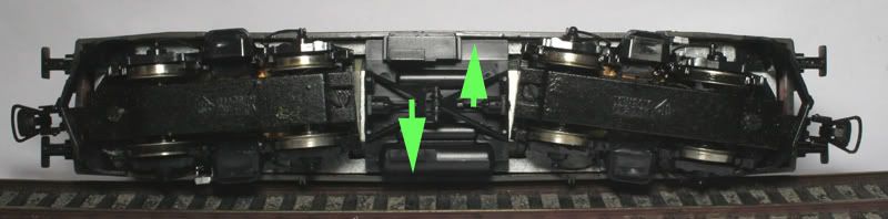
Move the body outwards from the middle and the tabs will release, lift the body upwards.
Remove the weights over the bogies, the power pick-up wires from the board and the retaining screws.
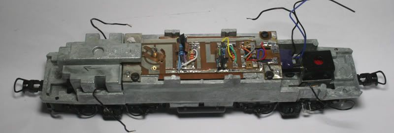
An ideal place for the decoder is under the end of the PCB board near the motor terminals and above the carden shaft.
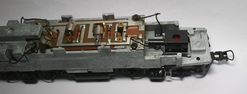
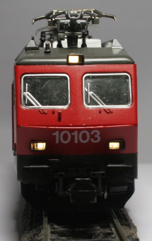
Light from the two lamps is transmitted down light pipes to the
front and rear of the loco. Each lamp will be replaced with a Warm White
and Red SMD LED.
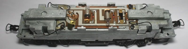
Remove all components from the PCB.
A few modifications to the PCB board.
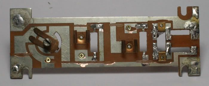
Cut the PCB tracks to isolate the switch from the circuit and also the supply for the lights.
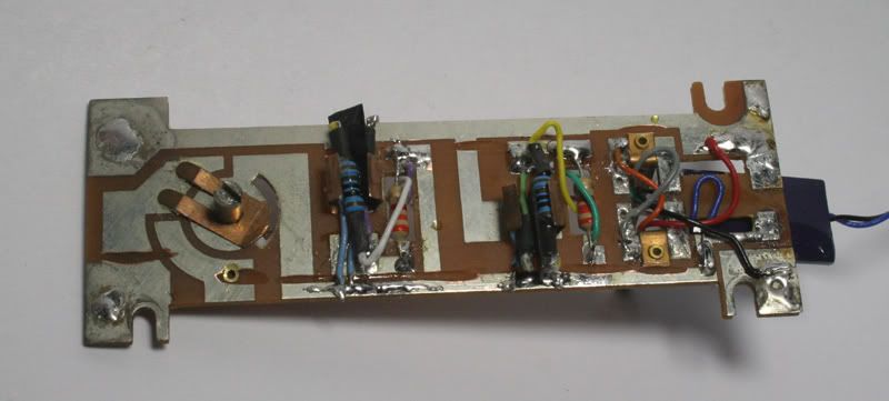
The blue wire supplying positive voltage from the decoder will be soldered to the lower track.
Below - SMD LEDs soldered in place a small piece of black card placed between the White and Red and glued in place with CA.
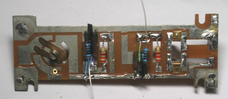
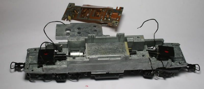
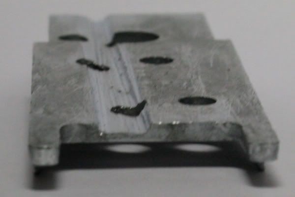
To fit the decoder wires in above the motor weight- grind a hollow in the bottom of the PCB board.
Remove all components from the PCB.
A few modifications to the PCB board.
Cut the PCB tracks to isolate the switch from the circuit and also the supply for the lights.
The blue wire supplying positive voltage from the decoder will be soldered to the lower track.
Below - SMD LEDs soldered in place a small piece of black card placed between the White and Red and glued in place with CA.
To fit the decoder wires in above the motor weight- grind a hollow in the bottom of the PCB board.
Mill out material from the weight that fits over the motor, leaving enough room for the wires to fit under the PCB.
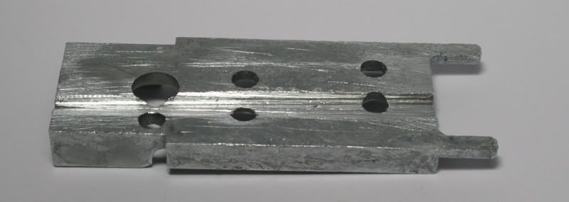
Groove milled in the weight to accommodate the decoder wiring.
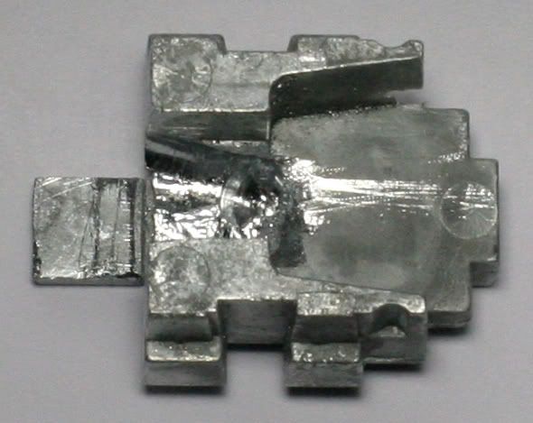
Mill out material from the end weight to accommodate the decoder, make sure there are no sharp edges, to wear away the decoder casing.
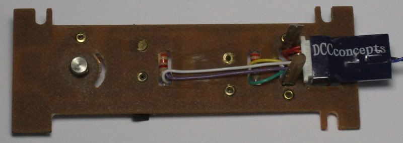
Close view of the decoder under the PCB


No comments:
Post a Comment