Adding Tail lighting to a BR103 Fleischmann # 4377
Hi All,
I promised to show this conversion and I added some Red SMD Tail-lights currently wired with the 2 function decoder but with a snip and a solder can be changed to a 4 Function ( Please when can I have some DCC Concepts decoders
 You lucky people in the UK
  )
)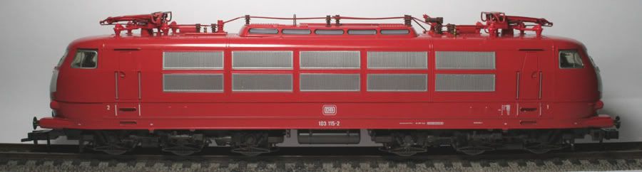
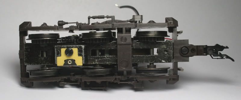
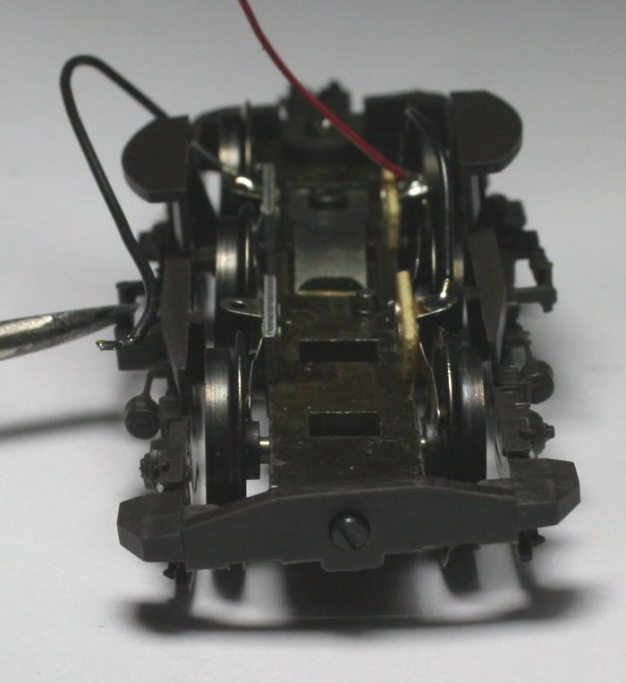
This Fleischmann model 4377 locomotive has power pick-up from eleven wheels great for consistent slow running these have near independent suspension. The middle driven axle has a spring mechanism on the axle, which allows movement up and down and side to side.
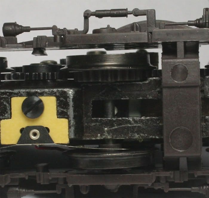
A bit difficult to see but the white dot is in contact with the axle and is connected to a spring the middle wheels can move up and down about 1mm and also side to side
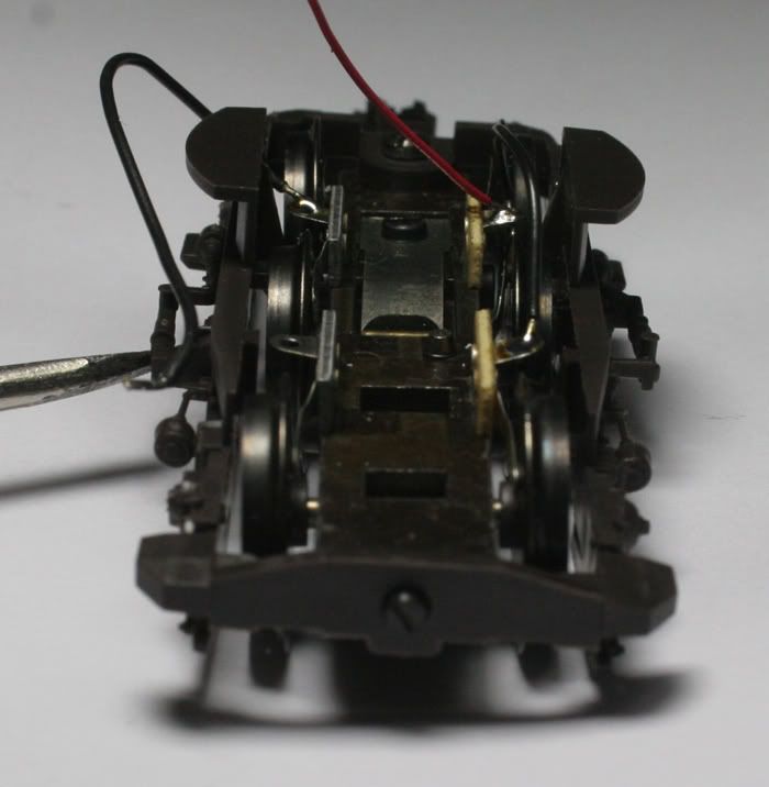
The non-powered bogie is also the same and can move as a unit, rotating in the horizontal direction to allow for twists in the track.
The analog model optionally can be powered from overhead catenary or from the rails. For DCC the catenary operation must be disabled.
The TCS T1 decoder is only a two-function decoder, on previous installs I have used a 4 function decoder to power the headlight at each end and the centre part of the locomotive, by installing two diodes on the circuit board both the white and yellow functions can switch the centre light on. I have also installed Red tail lighting .
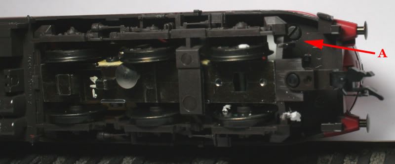
This locomotive has five small screws (Like the 4375), two at each end, and one central screw holding the body to the chassis. The four small screws are a bit difficult to get to – rotate the bogie to one side to access the screw and work your way around the locomotive chassis. Lift the body off the chassis.
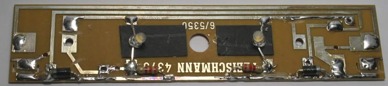
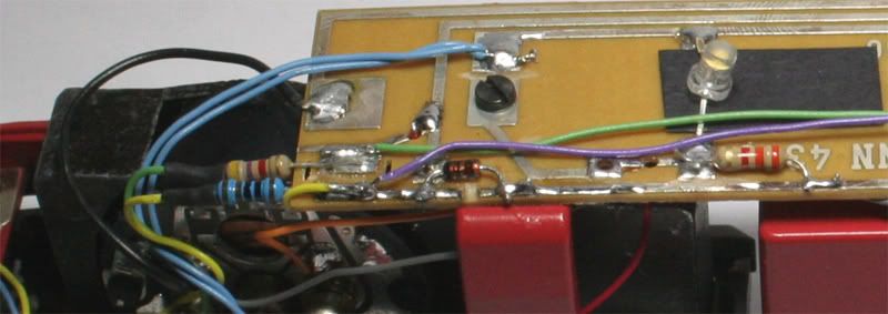
Above- Modify the circuit boards with a Dremel cut off wheel. From the top down the contact strips will be for the Black, Red, Blue and the bottom strip will have the Yellow on the left and the white on the right. The mounting screws ground the circuit to the chassis- make sure these are isolated too.
Below- PCB modified and components added.
Lighting
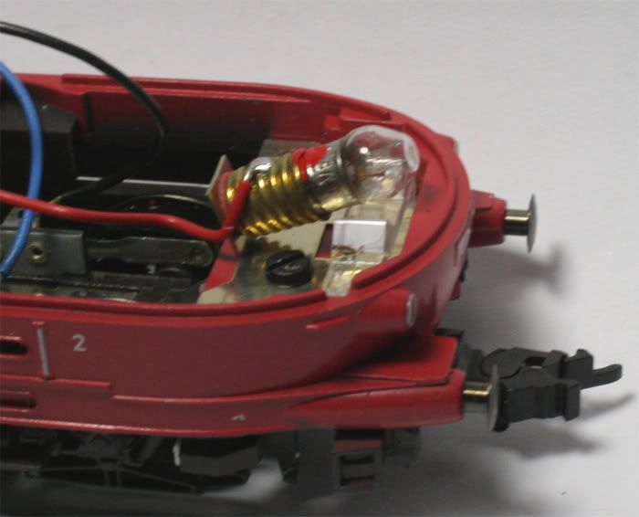
For this locomotive, I will add red SMDs to represent taillights. The SMDs will fit just under the original lamp holder as pictured below–before modification.
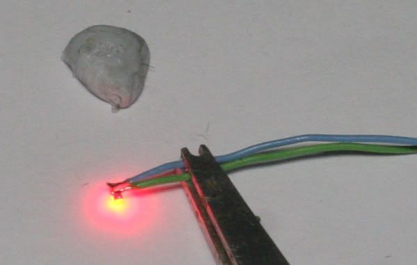
Above- Placing the SMD face down on a bit of blue tack –then pre tinning the wires and the SMD contacts makes soldering these tiny LEDs much easier – a magnifying lens helps too.
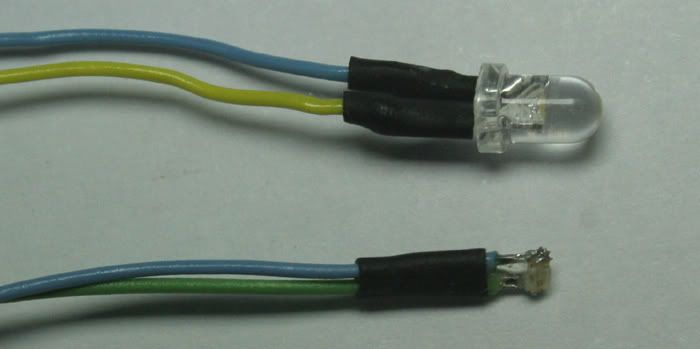
Above - compare the size difference between the 3mm t series LED and the 0603 SMD with wiring added.
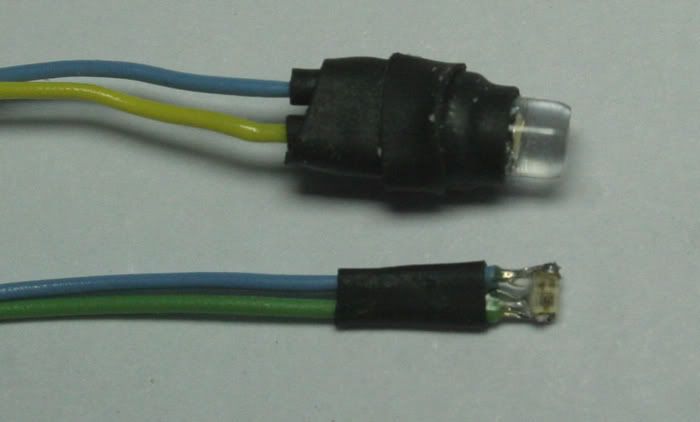
Above – a layer of heat shrink over the body of the LED and a second small ring of heat shrink will give the LED a snug fit in the original lamp-holder.
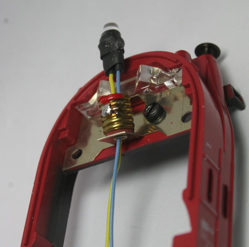
Above – Feed the wires from the LED through the base of the lamp-holder, then push the LED firmly into place – sometimes a drop of CA is needed to keep it locked in.
Below – Glue the SMD beneath the lamp holder – one small drop of CA is all that is required.
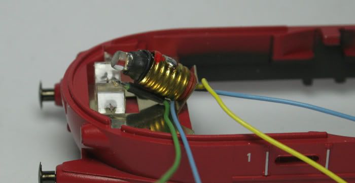
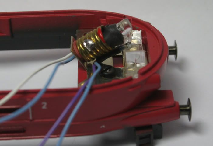
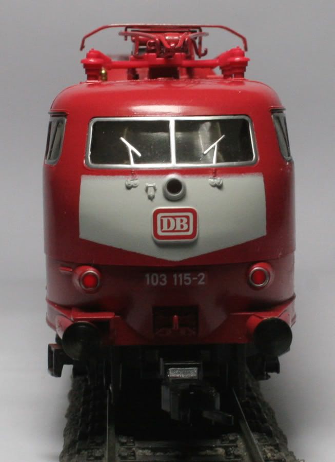
Above- Front light with red SMD glued under the lamp-holder.
Make use of the circuit board, wire the Red, Black, White, Yellow and Blue wires from the decoder harness to the appropriate points.
The decoder will mount under the circuit board.
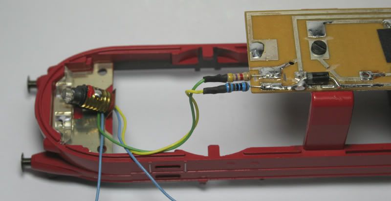
Soldering the Resistors to directly to the PCB keeps the wiring in place.
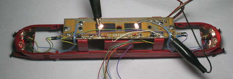
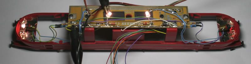
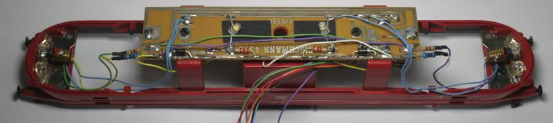
Above – Testing the lighting to make sure everything is wired correctly – this can be rewired easily to a 4 function decoder to have the tail-lights on a separate function.
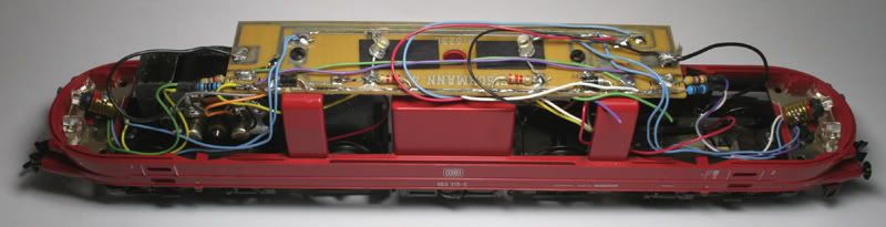
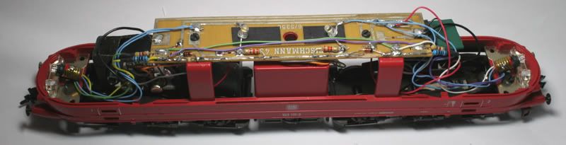
Above – all wiring complete ready for the decoder and the body to be replaced. The only snag was that the body would not quite go back on
, After moving wiring around and putting the body on a few times, I discovered that the Diodes (although fine in the older model) were just a bit to thick to allow the body to be replaced – luckily I had just received some new 100v fast acting diodes which were much smaller in diameter. 
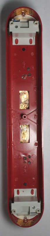
Before putting the body back on the chassis, glue some foil on the body to stop the LED’s direct light shining through the plastic, this also helps disperse the light better. Using this method, the LEDs have a more even light dispersal than the original bulbs in the centre section. Note also the contact springs have been removed and the switch arms cut short.
Paint the centre lamp pipe with a touch of White paint as the LED will be very bright through this lamp. Painting the underside of the cab floor will stop the cab lighting up as much when the lights are switched on.
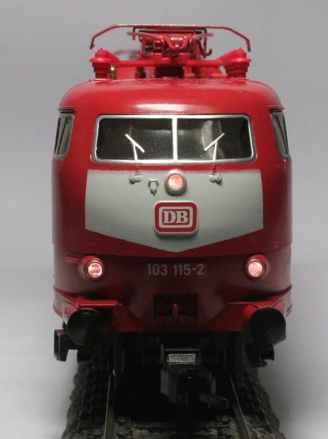
There is a tiny amount of red showing in the centre headlight - this is noticeable in total darkness only
It could be fixed by painting under the light pipes with black paint as currently there is a small reflective piece of metal.
This comment has been removed by the author.
ReplyDelete