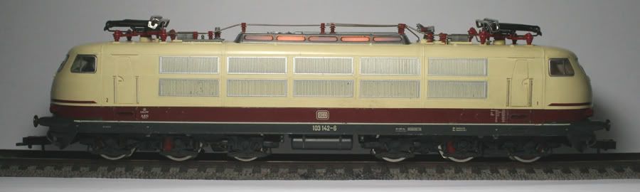
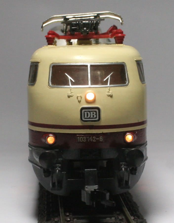
This Fleischmann model 4375 locomotive with the one-leg pantographs was produced only for two years (1980-1982) before being superseded by the 4376 with the red skirts. The analog model can be powered from overhead catenary or from the rails. For DCC the catenary operation must be disabled.
The TCS T1 decoder is only a two-function decoder, on previous installs I have used a 4 function decoder to power the headlight at each end and the centre part of the locomotive, by installing two diodes on the circuit board both the white and yellow functions can switch the centre light on.
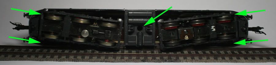
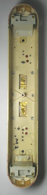
This locomotive has four small screws (Arrowed), two at each end, and one central screw holding the body to the chassis. The four small screws are a bit difficult to get to – rotate the bogie to one side to access the screw and work your way around the locomotive chassis. Lift the body off the chassis.
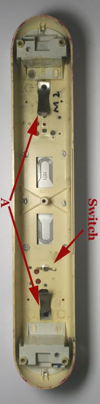
Remove the contact springs (A) linking the circuit board to the pantographs and the rotary switch contacts (cut these off).
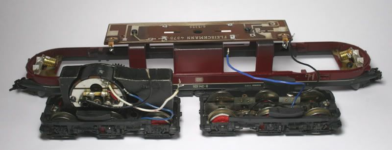
Remove all wiring and lamps from the circuit board , remove the lamps from the lamp holders at each end. Fleischmann use blue wire for one side of the pick-ups and black for the other. This locomotive has a driver in cab 2 so I thought to make that the normal forward direction. This makes the blue wire the right hand rail going forward.
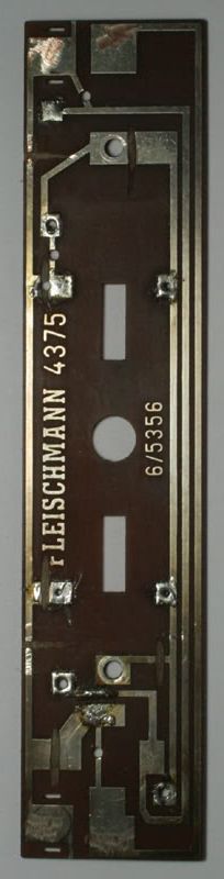
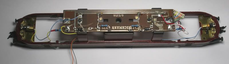
Above- Modify the circuit boards with a Dremel cut off wheel. From the top down the contact strips will be for the Black, Red, Blue and the bottom strip will have the Yellow on the left and the white on the right. The mounting screws ground the circuit to the chassis- make sure these are isolated too.
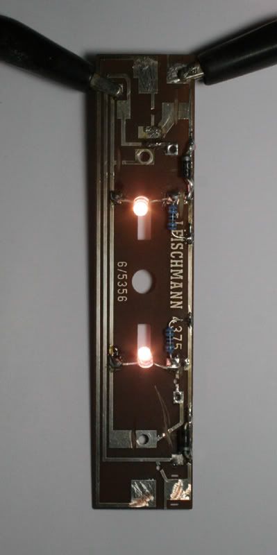
Above- Diodes and centre lights (LEDs powered through a 1 k Ohms resistor) pass the test.
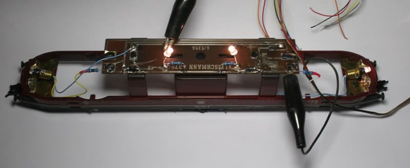
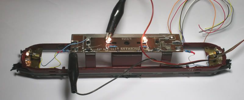
Above – White wire test. Below – Yellow wire test.
Make use of the circuit board wire the Red, Black, White, Yellow and Blue wires from the decoder harness to the appropriate points. The decoder will mount under the circuit board
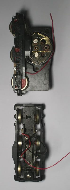
Replace the wires going to the pick-ups with the correct colour wire. The motor backplate can be modified or replaced with a backplate with insulated motor terminals. There is no continuity between the motor body and the wheels of the motorized bogie. The only pickups are on the near side of the bogie or right hand rail.
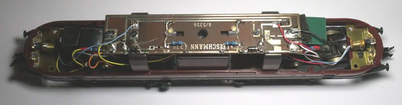
Above – Decoder mounted with some double-sided tape under the circuit board.
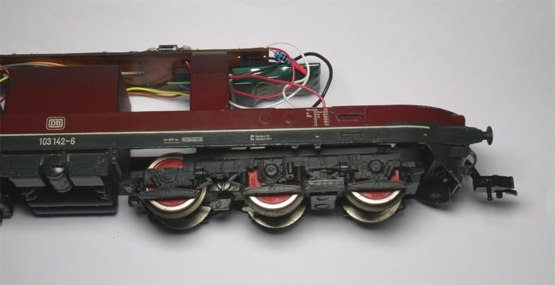
Before putting the body back on the chassis, glue some foil on the body to stop the LED’s direct light shining through the plastic, this also helps disperse the light better. Using this method, the LEDs have a more even light dispersal than the original bulbs in the centre section. Note also the contact springs have been removed and the switch arms cut short.
No comments:
Post a Comment