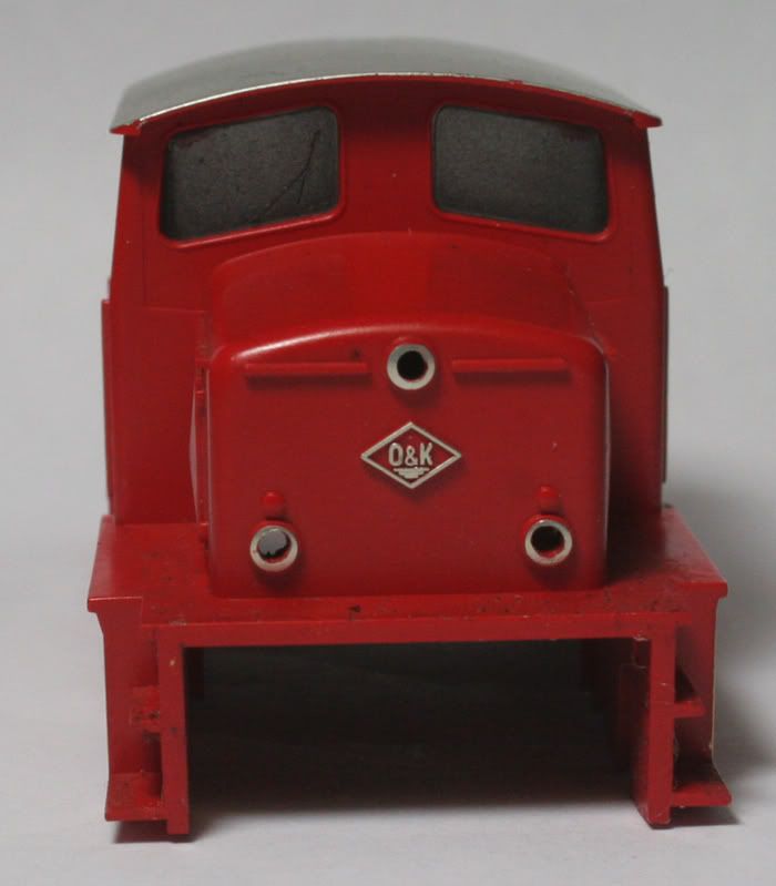
this little loco ready for a conversion to DCC and lighting , the original has no lighting.
 Reduced: 95% of original size [ 900 x 580 ] - Click to view full image
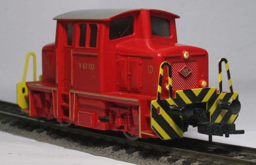
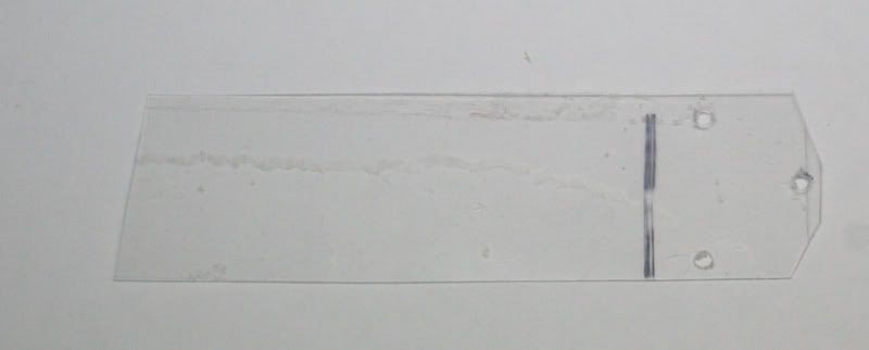
Firstly after pulling it apart , I made a little template of the lights
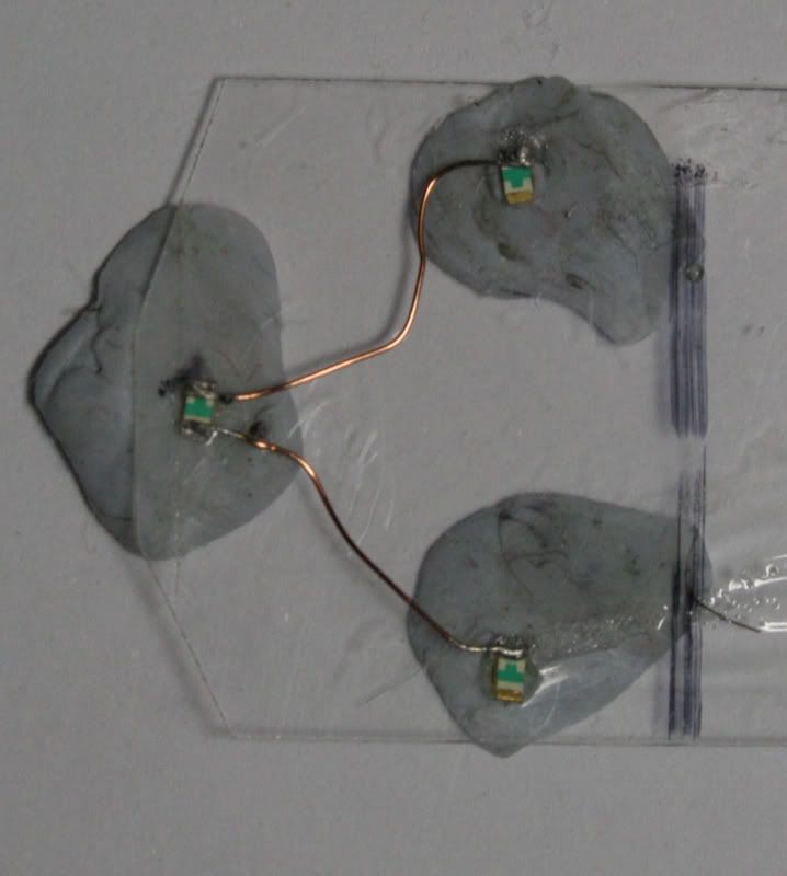
Then out with the Blu tack and some winding wire and SMDs
these are wired in series
Adding in the Blue and yellow wire time for a test
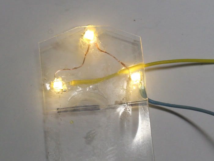
All works OK , I sandwiched the wiring and SMDs between two sheets of polycarbonate
for the other end I decided to try some thin card instead - less prone to heat damage and glue the polycarbonate to the back
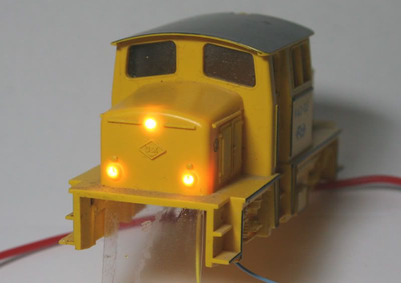
The Test Loco , looks OK Now to do the real thing
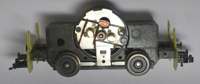
Next I Modified the back plate with a dremmel cutting disc , isolating different sections. quite a few cuts are required.
The motor body has to be isolated from the brush holder .
I cut two more groves later to have an area to solder the blue white and yellow wire with their resistors.
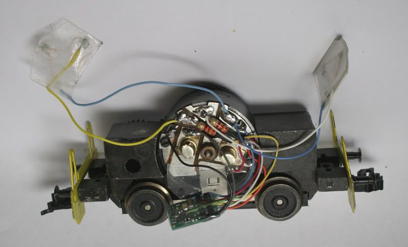
All the wiring in place and then the Orange wire came out..,
I had another M4 decoder , so I had a look where the wire was supposed to be soldered to.
Cut open some of the heat shrink and re-soldered the Orange back in place with the help of a magnifying lens

Put it on the Programming track an all was OK
So a bit more shrink was added to the decoder
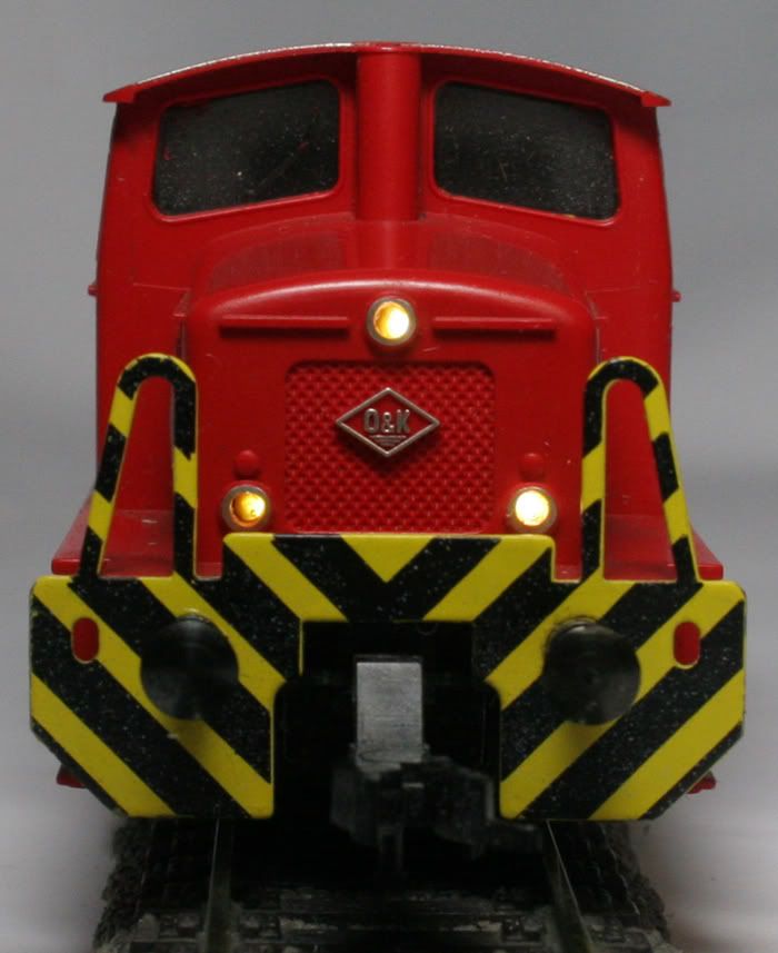
I drilled some small holes in the Red body
and the lights are are attached with double sided tape at each end of the chassis , the wires running over the top
I forgot to take a few photos , after the drama with the Orange wire.
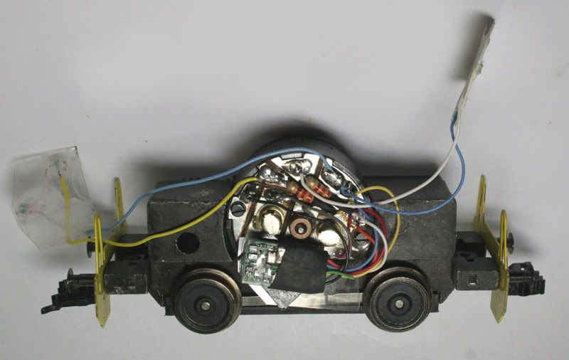
The decoder sits nicely next to the motor
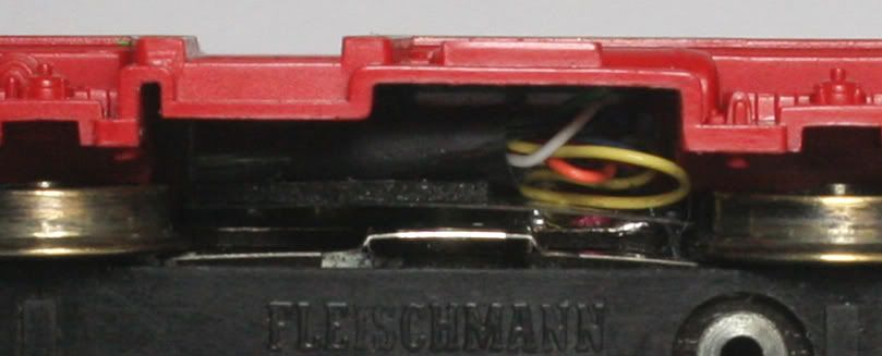
Just visible underneath
My first loco back in the seventies, nice.job.
ReplyDeleteWhat decoder is it?
ReplyDeleteIs it possible to become a plan i want to do the same.
Tim Germany Gelsenkirchen
Hi Tim, it is a TCS M4 decoder.
DeleteI want it to do with bipolar leds...like here...
ReplyDeletehttps://www.stayathome.ch/fleischmann_v42.htm
http://www.merte.de/werkbahn/photos_ok.htm
And thanks for your answere!
Tim
But one question...the cabels are conect the motor ...do you have a pic to better see where they are conect on ?
ReplyDeleteWhere the cabels are connect on the other side of the decoder?
ReplyDeleteAnd the resistors are where contact?
ReplyDeletehttps://www.sb-modellbau.com/details/H0-Motorisierungssatz-Fleischmann-V-42-OK
ReplyDeleteI find it ....but no "low price"
I cut the original backplate with a Dremel cutoff wheel. Made different sections to solder the resistors to from the resistors the wires go to the LEDs. Enlarge the photos to see what I have done.
ReplyDeleteThis is all connected with NMRA standard wiring.
ReplyDeleteBlack to the chassis of the lock (Right hand rail)
Red to the left hand rail pick up.
Orange to the isolated +ve motor contact
Grey to the -ve contact.
Blue is common for the lights
White for the forward lights
Yellow to the reverse lights
Thank you!
ReplyDeleteI have buy the original plate from the fleischman company and i need not it to cut. But one question please...
ReplyDeleteThe two resistors and conect with the lights and from the decoder ...on the other side only with the cabels?
I hope it is to understand my englisch!?
Fleischmann 504715 Motorlagerschild " Massefrei "
ReplyDeletehttps://skydrive.live.com/redir?resid=D3B6CDBA2DEF7725!123&authkey=!AFgffvvoLi6U9v0
ReplyDeleteRepair guide...the resistors are connect by the decoder with "schrumpfschlauch"(black isolation)?
And:
What material is it on the screw to isolate the decoder on the place?
Sorry i want it to know it looks good and i find it is a good way ! Very nice!
Sorry...schrumpfschlauch is in englisch like "shrinking tube"!? (Google translate)
ReplyDeleteThe next question...what lights are you use? Smd i think!??...what for Model number? I want to use bipolar smd led.
ReplyDeleteHeat shrink tube is the English
ReplyDeleteThe smd led was a 603 from memory but I could be wrong
The reason I used the original motor back plate was to have somewhere to solder connecting wires and resistors to so there is less loose wiring
ReplyDelete